
Beersheba
RENEWED EXCAVATIONS
As part of the development of the site by the National Parks Authority from 1993 to 1995, the well on the southern slope and the water supply system on the northern part of Tel Beersheba were excavated. The excavations were directed by Z. Herzog of the Institute of Archaeology at Tel Aviv University.
THE WELL ON THE SOUTHERN SLOPE
The well, 1.8 m in diameter, was found outside the line of the city’s fortifications at a depth of 2 m below ground. Down to a depth of c. 5 m, the well was hewn through layers of conglomerate and lined with dressed limestone slabs. The lower part of the well was hewn through chalk. The excavation continued down to 1 m below water level (reached at a depth of 69 m) without reaching the bottom.
This well was hewn into the tell’s southeastern slope in the Iron Age, around the time the site became a permanent settlement. It served as the main water source for strata IX to VI (tenth century BCE). When a fortified city was first built on the site (stratum V), the well was left outside the fortifications. Clearly, the well was the only abundant source of water for the city and served both its inhabitants and visitors. It remained in use through the Iron Age II and to the end of the Hellenistic period.
THE WATER SUPPLY SYSTEM INSIDE THE CITY
During the second season of excavations (1970) a wide staircase was discovered on the northeast end of the tell. Y. Aharoni was of the opinion that this was the beginning of a spiral staircase belonging to a water system similar to those at Megiddo, Gibeon, and Hazor.
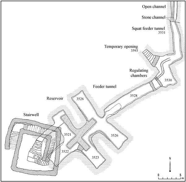
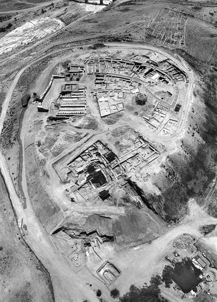
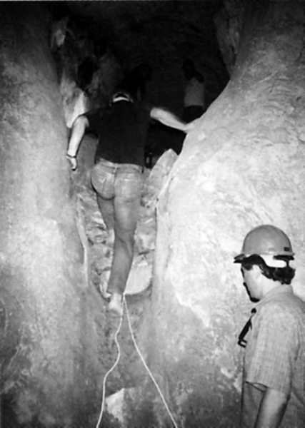
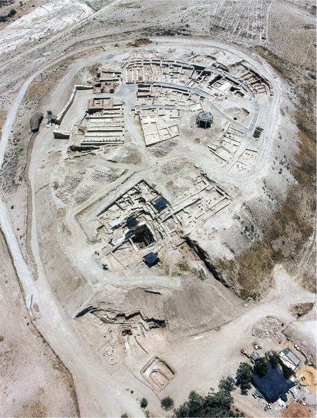
Twenty-four years later, in 1994, the excavation of the water system was renewed. The work continued for a year and a half, exposing the fortifications that encircled it and the buildings adjacent to it. The remains of this water system were exceptionally well preserved and constitute the most impressive remains at Tel Beersheba. The excavations supported most of Y. Aharoni’s conjectures, namely that the water system was indeed constructed contemporaneously with the first fortified city (stratum V), and the water source was not dependent on groundwater, but was connected to a series of underground pools that were filled from the outside. The water system has four main parts: (1) a square stairwell in a shaft with walls reinforced by masonry; (2) an array of underground cisterns; (3) a feeder tunnel that filled the pools; and (4) an opening used while the system was being constructed and sealed when the project was completed. Both chronology and stratigraphy attest to centuries-long use of the water system. During this extensive period of use, the system underwent certain structural and functional changes.
THE FIRST PHASE. The first phase of the system consisted of a subterranean reservoir fed by a system of tunnels. The reservoir was reached from within the city by a deep stairwell.
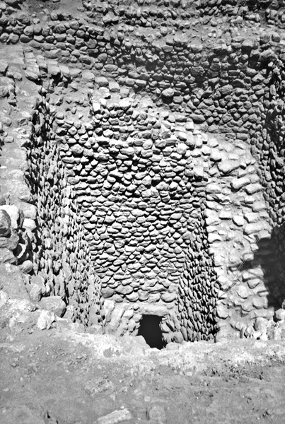
The Stairwell. A square shaft, 12 by 12 m, descending to a depth of 15 m, was hewn for most of its depth through the conglomerate layer covering the hill. This is a brittle and unstable rock and it was therefore necessary to add slanted retaining walls to support the stairs. Both retaining walls and stairs were, of course, constructed from the bottom up and the builders would have needed ladders and probably scaffolding as well. The building material consisted of large nodes of bulbous limestone and blocks of flint. The largest stones set into the retaining walls’ foundation levels are 80 cm long and weigh 200 kg. Those on the upper levels are medium-sized (20–30 cm long). The stones were laid in fairly straight courses, although not of a uniform height. The slant of the walls was achieved by recessing each course a few centimeters back from the one below it. On the western side, the wall was set back, in addition to this slant, by two more prominent indents, each measuring c. 25 cm, at c. 5-m intervals. The inside wall of the staircase facing the center of the shaft has, for the most part, collapsed; however, the shape of the surviving stones indicates that the stairs had a stone balustrade, an essential safety feature in a 15-m shaft. Similar rock-cut balustrades were found in the staircases of the entrance shafts to the water systems at Hazor and Gibeon. Five flights of stairs descend along the shaft walls. Both the shaft and the width of the stairs narrow as one descends.
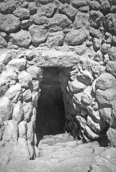
The Reservoir. The underground part of the water system consists of a reservoir comprising a central cistern with five side cisterns cut into the local chalk, and a system of feeder tunnels (described below). The main axis of the water system is southwest to northeast. The entrance tunnel leading from the stairwell to the reservoir is approximately 1.5 m wide, 1.8 m high, and 5 m long. The tunnel descends via stone stairs and eventually penetrates the chalk layer. The stairs lead to the reservoir.
The underground portion of the water system is exceptionally well preserved. Aside from a thick layer of silt in the second cistern (3522), some rock fragments that had fallen from the ceiling, and scattered fallen lumps of plaster, the entire reservoir remained as it was when sealed some two thousand years ago. All of the walls of the reservoir were coated with thick layers of plaster (total thickness 10 cm) up to a height of 4 m. Above that, the natural bedrock remained exposed, slanting toward the center of the reservoir, thereby reducing the ceiling span and increasing the stability of the roof.
An examination of the reservoir and the various wall surfaces clearly shows that it underwent modifications during its period of use. Yet it is still possible to reconstruct the reservoir’s original plan: a central cistern 15 m long and 3 m wide, from which four side cisterns branch out perpendicularly, two on each side. Each of the side cisterns measures c. 6 by 4 m. The estimated volume of the central cistern is 270 cu m and that of the side cisterns is 430 cu m. The total storage capacity is thus c. 700 cu m.
The Feeder System. The system that fed the reservoir consisted of four parts (here described in order of the water flow): an open channel (only partly excavated), a squat feeder tunnel, two regulating and settling chambers, and a high feeder tunnel. The total length of the feeder system was nearly 50 m.
Five meters of the open channel were exposed on the hill’s northern slope. It was cut into the conglomerate layer and is c. 2 m wide and c. 1.5 m deep at its far end. A stone-built channel was built within the open channel in a second stage. The open channel was joined to an opening in the chalk layer, c. 2 m below today’s ground level, from which the squat feeder tunnel (3531) issues forth. The elevation of the channel at the breach point is 287.7 m above sea level, 7.9 m higher than the level of the floor of cistern 3522 (the lowest part of the reservoir). It may be supposed that in the first stage the opening was blocked by a stone grating in order to prevent entrance by adversaries; D. Ussishkin found grill-like stone barriers at the entrance of the city gatehouse drainage channel at Lachish. The squat feeder tunnel is not straight, following a southerly course for the first 10.5 m, then making a 110-degree turn and continuing for another 6 m until it reaches the smaller regulating chamber. The height of the tunnel is only 1.3 m; it is 1.2 m wide at the beginning, but reaches a width of 2.2 m in the vicinity of the regulating chamber. The ceiling is shaped like a barrel vault. The structure of the squat feeder tunnel provides evidence for the stages in construction of the entire project. When the stonecutters began working on the tunnel’s upper part, they apparently hewed it to its entire planned width. As they worked downward, they seem to have decided to facilitate their work by making the tunnel’s lower part as narrow as possible while still allowing passage. Only the bottom of the squat feeder tunnel channel was plastered.
The squat feeder tunnel leads into the small (2-by-2-m) regulating chamber. Water-flow regulation in the chamber was achieved by blocking the direct course of the flow; the water exited the chamber through an opening in the wall placed at a right angle to the flow. At the point where the squat feeder tunnel enters the regulating chamber, the workers created a drop of c. 80 cm. This chamber thus also served as a sump for pebbles and soil swept along with the water. On the chamber’s northwestern side, a stone wall blocks the temporary opening used at the time of the system’s construction (see below).
The water then flowed into the large regulating chamber (3530), a square (3.7-by-3.5-m and 2-m-high) room whose walls were plastered up to the ceiling. Here, too, the flow of water was diverted; entry into the high feeder tunnel necessitated another right-angle turn to the southwest. The two chambers and the opening connecting them were clearly intended to slow the flow of water and reduce the amount of silt and the possible damage it could cause. The water that reached the reservoir was thus relatively clean.
The large regulating chamber is connected to the underground reservoir by the high feeder tunnel (3528). This straight tunnel is 17 m long, 2.2 m wide, and up to 2.2 m high. Its roof is cut in the shape of a barrel vault, its floor flat along its entire length, sloping moderately downward, and 4.68 m higher than the reservoir floor at the tunnel’s end. A slanted chute was cut there in order to prevent the water from falling from such a great height and damaging the installation. The tunnel’s floor and walls are plastered up to the springing of the ceiling arch. The ceiling has survived intact and the stonecutters’ tool marks are still visible.
The stone-built retaining wall and ceiling in the small regulating chamber’s northern wall indicates that there used to be an exit at this point (3593). In order to understand the wall’s function and its relation to the project, it was decided not to dismantle it from the inside but rather expose what lay outside first. Therefore, an additional excavation area was set up at the bottom of the tell, exposing a square shaft (2 by 2 m) with rounded corners. Inside the shaft, stairs had been cut into the natural rock on the west side. At the bottom of the shaft, the external side of the sealed wall was found, supporting the stone slabs which served as the ceiling on the north side of the small regulating chamber. This provided conclusive proof for the hypothesis that the sealed wall blocked an exit that was cut while the system’s construction was in progress, for the purpose of facilitating work, particularly the removal of waste. After construction had been completed, the opening in the wall was sealed, the ceiling covered with slabs of stone, and the entire shaft filled with a thick layer of soil in order to prevent its discovery.
By calculating the volume of removed rock and the amount of masonry and plaster, it is possible to estimate the amount of time it took to create the water supply system. Considering the limited space inside the installation, it is assumed that the work was done by two teams of 30 workers, each team working at one end of the system. Another team, estimated at 40 workers, conducted the transportation of construction materials and removal of rubble. Assuming a total of 100 workers, the project could have been completed within three or four months.
The Water Source. Y. Aharoni originally proposed that the reservoir was filled with rainwater collected from the eastern hill. However, the feeder tunnels issue from the north, indicating that the source was the floodwater in
Stratigraphy and Dating of the First Phase (strata V–IV). The buildings of stratum VII clearly predate the water system, as the stratum’s buildings were damaged by the construction of the stairwell. The construction of the water system as part of the fortified city of stratum V makes sense both in light of the architectural affinity between the stairwell and the city wall of this stratum, as well as the fact that the glacis of stratum V contains material originating from rock layers removed when the water reservoir was built. The fortified city of stratum V was surrounded by a solid wall, 3.5–4.2 m thick. The water system’s staircase shaft is adjacent to the wall’s internal face. On the tell’s northeast corner, the wall included a protruding 8.4-m-long tower, which commanded the approach to the city gate on one side and the entrance to the water system on the other. Two rooms uncovered in the tower’s vicinity may have served the guard entrusted with defending this strategically important corner.
The destruction of the city of stratum IV brought the collapse of the water system together with damage to the city walls and outer gate. The destruction may have been caused by an earthquake in the middle of the eighth century BCE (Am. 1:1; Zech. 14:5).
THE SECOND PHASE. Evidence for fundamental modifications of the water supply system consists of walls constructed inside the underground reservoir’s central chamber and changes in the organization of the system’s feeder tunnels.
Stratigraphy and Dating of the Second Phase (strata III–II). After the destruction of stratum IV, the city was restored with a completely new system of fortifications (stratum III). The city wall’s brick superstructure was dismantled and replaced by stone foundations for a casemate wall. In the vicinity of the water system, most of this casemate wall has been washed away or plundered, but its course can still be reconstructed. Near the northwestern corner of the stairwell a stone rainwater drainage channel was discovered. The existence of this channel proves that when the water system was in use, an effort was made to prevent rainwater from entering the reservoir.
The changes made in the water system’s second phase were necessitated by the collapse of the ceiling, probably as a result of the same earthquake that destroyed the rest of the city. The water system’s reconstruction was part of the renewal of the settlement in stratum III. For the restoration work, the squat feeder tunnel was opened in order to remove debris, and retaining walls were built to prevent the further collapse of the ceiling. The reservoirs would certainly have been coated at this time in a new layer of plaster, sealing any cracks in the walls. The additional walls reduced the reservoir’s capacity from 700 to c. 600 cu m. The changes to the feeder tunnels, particularly the addition of stone-built channels, should also be ascribed to this phase. Both the well and water system continued operating without change through the period of stratum II.
THE THIRD PHASE (stratum H2). When the fortified city of stratum II was destroyed at the end of the eighth century BCE, the site ceased functioning as a fortified city and was only resettled after roughly a 300-year hiatus. The riverbed probably continued receding from the site during this time, the feeder tunnel became blocked, and the stairwell at least partially filled with debris. When the site was reinhabited, the water system no longer functioned as a reservoir for floodwaters directed toward it from outside the tell, but for rainwater that fell upon the tell into the stairwell shaft and its vicinity. This phase began during the Persian period and lasted until the end of the Hellenistic period.
Cistern 3522 is the only one in the reservoir used in this phase, and it was found silted to a height of 1.4 m. This accumulation probably resulted from the seepage of rainwater carrying silt in the time period after the stairwell collapsed until it was filled in.
THE CESSATION AND BLOCKAGE OF THE WATER SYSTEM. The excavation of the fill in the stairwell yielded evidence on the nature of its blockage. In the upper part of the fill (from a depth of 4 m to c. 6 m from the top of the shaft), a horizontal soil layer was found. Underneath were layers of soil inclined at a 33-degree angle, poured down from the shaft’s southern side and continuing to a depth of 11 m from the top of the shaft. Under them were layers of soil mixed with pebbles, inclined at an angle of 20 degrees and continuing to a depth of 13 m from the top of the shaft. The steep angle of the fill layers above the collapsed rocks points to the swift and deliberate pouring of earth into the shaft. The horizontal top layer shows that the soil was leveled in the last stage of the filling of the cavity.
The dates of the finds unearthed in the various parts of the fill present an interesting case of “inverse stratigraphy,” with the later finds appearing at the bottom of the shaft. The most recent item in the fill, a city coin of Ashkelon dating to the year 50 BCE, was found in the lower part of the shaft, at the point where the entrance channel opened into the underground reservoir. Also found in the shaft were some early Nabatean coins (from the reign of Aretas II or Aretas III) dating from 110 to 71 BCE. Finds dating to earlier periods were found in the higher layers of the fill, including amphora handles with rosette seal impressions, the earliest of which is dated to c. 200 BCE (according to M. Fischer).
Thus the shaft was in use until at least the mid-first century BCE, its collapse occurring after the year 50 BCE. To this same period may be ascribed the destruction of other water supply systems in the Beersheba Valley: the collapse of the well at Tel Beersheba and the underground reservoir at Arad, and perhaps also the well at Arad. These were probably all destroyed by the same event. There is evidence for a strong earthquake in this region that caused considerable damage in Jericho, Qumran, and Masada, and Josephus mentions a great earthquake in the year 31 BCE. This earthquake could well have been the cause of this widespread destruction, also ruining the water systems at Tel Beersheba and Arad.
The deliberate infilling of the shaft probably occurred as part of the construction of the Herodian palace (stratum H1). The finds from the upper part of the shaft indicate that the material for the fill was taken from the ruins of the Hellenistic settlement (stratum H2). This brought an end to Tel Beersheba’s impressive water supply system, which remained buried until its rediscovery in modern times. Once it went out of use, the inhabitants of the site were forced to collect rainwater in pools constructed for this purpose, such as that in the inner courtyard of the Herodian period palace (stratum H1). In the Roman (stratum R) and Early Islamic (stratum Ar) periods, rainwater was collected in a pool dug next to the fortress, which supplied the needs of the small garrison stationed at the site.
ZEEV HERZOG
The Chalcolithic Settlements
Color Plates
RENEWED EXCAVATIONS
As part of the development of the site by the National Parks Authority from 1993 to 1995, the well on the southern slope and the water supply system on the northern part of Tel Beersheba were excavated. The excavations were directed by Z. Herzog of the Institute of Archaeology at Tel Aviv University.
THE WELL ON THE SOUTHERN SLOPE
The well, 1.8 m in diameter, was found outside the line of the city’s fortifications at a depth of 2 m below ground. Down to a depth of c. 5 m, the well was hewn through layers of conglomerate and lined with dressed limestone slabs. The lower part of the well was hewn through chalk. The excavation continued down to 1 m below water level (reached at a depth of 69 m) without reaching the bottom.